![]()
|
|
|
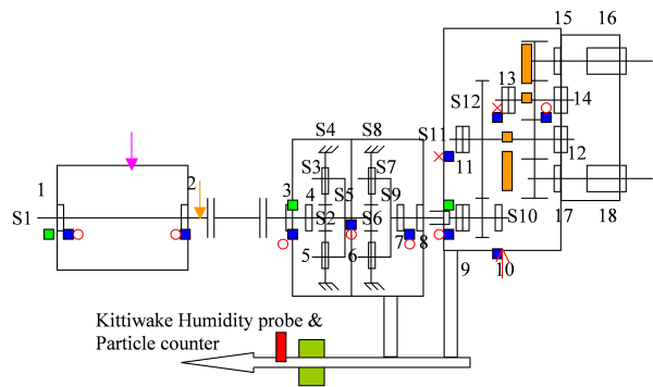
Technology: Creating A Machine Database The basic building block of a machine as we have programmed it, is a group of “shafts” which have “bearings” and “gears” mounted on them as the drawing shows. Numbering starts at the non drive end of the driver (motor in this case). Shaft 1, S1, motor, no teeth, bearings 1 & 2 (unknown in this case) see drg & figure 1. Shaft 2, S2, epicyclic input shaft, 22 teeth, bearing 3 (6024), brg 4 (6224), see drg & figure 1. Shaft 3, S3, epicyclic planet shaft, 74 teeth, bearing 5 (INA SL182215), see drg & figure 1. Shaft 4, S4, epicyclic ring gear, 164 teeth, stationary, no bearings, see drg & figure 1. And figures 2, 3 & 4 for remaining gear and bearing numbers. Typical rolling mill rougher stand
(S2) Sun 1 = 20 Hz (6024, 6224) Ratio = 8.455:1 (sun 22t, planet 71t, fixed ring 164t) Epicyclic tmf 1 = 387.96 Hz Planet speed = -3.099 Hz (S3) (INA SL182215) (Stationary ring S4) Carrier = 2.366 Hz = (S5) (planet pass freq = 2.366 x 3 = 7.098 Hz) Ratio = 4.857:1 (sun 21t, planet 30t, fixed ring 81t) (same as Sydney) Sun 2 = 2.366 Hz (S6) Epicyclic tmf 2 = 39.46 Hz Planet speed = -0.828 Hz (S7) (NCF3020) (Stationary ring S8) Carrier = 0.487 Hz = (S9) (NJ244, NCF 2956 V) (planet pass freq = 0.487 x 3 = 1.461 Hz) Main gearbox = 4.800:1 (S10) 0.487 x 20t = 9.74 Hz, tmf 3, brg 9=32038, brg 10=24034 9.74/96 = 0.1015 Hz = (S11) brg 11=32044, brg 12 & 14 =24138, brg 13=32038 0.1015 x 29t = 2.9423 Hz, tmf 4. (overall ratio = 197.116=7:1) Bar in mill for 8 turns of the output shaft. Figure 1
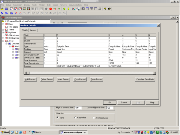
Figure 2
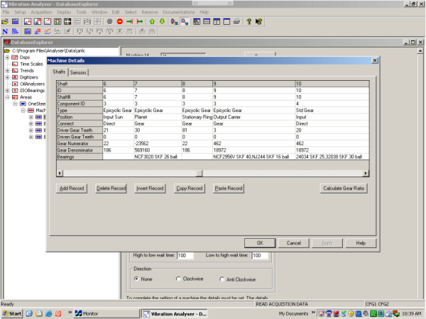
Figure 3
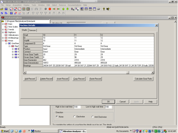
Figure 4
|