![]()
|
|
|
Technology: Sync and Non Sync Vibration Our multi channel frequency analysis of tachometer and vibration signals, along with the gear tooth numbers, allows us to know exactly which spectral lines are exact harmonics of each shaft speed, thus allowing exact calculation of sync and non sync vibration in each chosen spectral band. With the exceptions of pure thrust ball or parallel roller bearings, bearing ball pass frequencies are non integer values, because the inner and outer rings have different circumferences. So bearing vibration harmonics fall on non sync lines of the shaft they support. With multi shaft gearboxes there will be combinations of other shaft harmonics that will fall by chance on a ball pass frequency of a bearing on another shaft, but most of the ball pass harmonics will remain non sync to all shafts. There is also slight and variable slippage within the rolling elements, especially as damage increases, so the calculated ball pass frequencies change, but the sync, non sync separation is still clear and trendable. The non synchronous vibrations from electric motors also needs to be taken into account in the automated assessment of bearing faults based on non sync vibration in the band. To confirm the automated diagnosis, a skilled person can overlay the likely ball pass frequencies stored in the Tensor database on the non sync harmonics, and allowing for all the variations with experience, make a judgment. A real spectrum is quite complex so to simplify things, the Velocity spectrum below shows 5 harmonics of the high speed shaft (S1), 20 harmonics of both intermediate (S2) and low speed shafts (S3) in this 3 gearbox, reducing in severity with frequency. A bearing fault at harmonics of 4.3x (S2) second shaft speed are shown on non synchronous lines (not harmonics of any shaft speed). 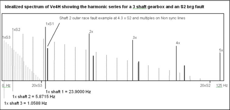
In the simple example, measured at the intermediate shaft (S2) bearing, the effects of the first 20 harmonics of 3rd shaft speed are small in magnitude and barely effect the intermediate shaft speed beyond it’s 4th harmonic and ball pass frequencies. Also, there are only 4 harmonics of the input shaft speed, so there are plenty of spectral lines to be counted as synchronous for shaft and gear related faults, and non synchronous lines for bearing faults. When measuring at the output shaft (S3) bearing we would only include 20 harmonics of (S3) and look for 4 harmonics of the output shaft ball pass frequency, which would stretch across the whole spectrum. There are would be no input (S1) harmonics, only 4 intermediate shaft (S2) harmonics, and no (S2) ball pass frequencies in the spectrum, allowing the simpler detection of any (S3) bearing fault harmonics. The real world measurement range is about 100x of each shaft speed, and beyond 100x of any shaft speed we assume it’s sync and non sync vibration is negligible. This is all adjustable in the data base set up. A key part of the method to is to keep sync and non sync line resolution high by using a large number of spectral lines, and typically a steel rolling mill gearbox with 6 different shaft speeds will need 6400 lines. If the machine speed wanders during sampling the spectrum will be smeared and the sync, non sync line model will not work. To overcome this problem we “resample” the whole data block with a “cubic spline” curve fitter, to produce a spectrum in terms of “ shaft orders”. Read on… |